Generic Setup for Testing Static INL and DNL
INL and DNL can be measured with either a quasi-DC voltage ramp or a low-frequency sine wave as the input. A simple DC (ramp) test can incorporate a logic analyzer, a high-accuracy DAC (optional), a high-precision DC source for sweeping the input range of the device under test (DUT), and a control interface to a nearby PC or X-Y plotter.
If the setup includes a high-accuracy DAC (much higher than that of the DUT), the logic analyzer can monitor offset and gain errors by processing the ADC's output data directly. The precision signal source creates test voltages for the DUT by sweeping slowly through the input range of the ADC from zero scale to full scale. Once reconstructed by the DAC, each test voltage at the ADC input is subtracted from its corresponding DC level at the DAC output, producing a small voltage difference (VDIFF) that can be displayed with an X-Y plotter and linked to the INL and DNL errors. A change in quantization level indicates differential nonlinearity, and a deviation of VDIFF from zero indicates the presence of integral nonlinearity.
Analog Integrating Servo Loop
Another way to determine static linearity parameters for an ADC, similar to the preceding but more sophisticated, is using an analog integrating servo loop. This method is usually reserved for test setups that focus on high-precision measurements rather than speed.
A typical analog servo loop (see Figure 2) consists of an integrator and two current sources connected to the ADC input. One source forces a current into the integrator, and the other serves as a current sink. A digital magnitude comparator connected to the ADC output controls both current sources. The other input of the magnitude comparator is controlled by a PC, which sweeps it through the 2N - 1 test codes for an N-bit converter.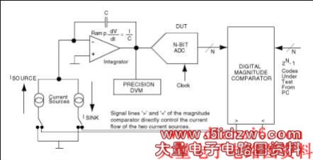
Figure 2. This circuit configuration is an analog integrating servo loop.
If the polarity of feedback around the loop is correct, the magnitude comparator causes the current sources to servo the analog input around a given code transition. Ideally, this action produces a small triangular wave at the analog inputs. The magnitude comparator controls both rate and direction for these ramps. The integrator's ramp rate must be fast when approaching a transition, yet sufficiently slow to minimize peak excursions of the superimposed triangular wave when measuring with a precision digital voltmeter (DVM).
For INL/DNL tests on the MAX108, the servo-loop board connects to the evaluation board through two headers (see Figure 3). One header establishes a connection between the MAX108's primary (or auxiliary) output port and the magnitude comparator's latchable input port (P). The second header ensures a connection between the servo loop (the magnitude comparator's Q port) and a computer-generated digital reference code.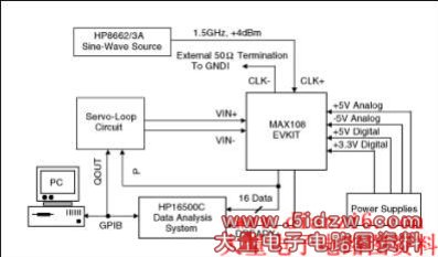
Figure 3. With the aid of the MAX108EVKIT and an analog integrating servo loop, this test setup determines the MAX108's INL and DNL characteristics.
The fully decoded decision resulting from this comparison is available at the comparator output P > QOUT, and is then passed on to the integrator configurations. Each comparator result controls the logic input of the switch independently and generates voltage ramps as required to drive succeeding integrator circuits for both inputs of the DUT. This approach has its advantages, but it also has several drawbacks:
- The triangular ramp should have low dV/dt to minimize noise. This condition generates repeatable numbers, but it results in long integration times for the precision meter.
- Positive and negative ramp rates must be matched to arrive at the 50% point, and the low-level triangular waves must be averaged to achieve the desired DC level.
- Integrator designs usually require careful selection of the charge capacitors. To minimize potential errors due to the capacitors' "memory effect," for instance, select integrator capacitors with low dielectric absorption.
- Accuracy is proportional to the integration period and inversely proportional to the settling time.
A DVM connected to the analog integrated servo loop measures the INL/DNL error versus output code (Figures 4a and 4b). Note that a parabolic or bow shape in the plot of "INL vs. output code" indicates the predominance of even-order harmonics, and an "S shape" indicates the predominance of odd-order harmonics.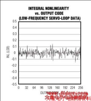
Figure 4a. This plot shows typical integral nonlinearity for the MAX108 ADC, captured with the analog integrating servo loop.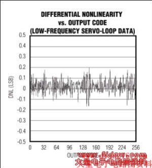
Figure 4b. This plot shows typical differential nonlinearity for the MAX108, captured with the analog integrating servo loop.
To eliminate negative effects in the previous approach, you can replace the servo loop's integrator section with an L-bit successive-approximation register (SAR) that captures the DUT's output codes, an L-bit DAC, and a simple averaging circuit. Together with the magnitude comparator, this circuit forms a SAR-type converter configuration (see Figure 5 and "SAR Converter" discussion below), in which the magnitude comparator programs the DAC, reads its outputs, and performs a successive approximation. Meanwhile, the DAC presents a high-resolution DC level to the input of the N-bit ADC under test. In this case, a 16-bit DAC was chosen to trim the ADC to 1/8LSB accuracy and obtain the best possible transfer curve.