Keep Power Consumption in Check with Low-Power Comparators that Autosense Plugged-In Accessories
Abstract: Portable electronic devices usually include a single 3- or 4-connector jack which can be a stereo headphone jack, a mono headphone jack with microphone input and hook switch, or a stereo headphone jack with microphone/hook-switch combination. Tiny, ultra-low-power comparators like the series can be configured in various ways not only to consume negligible power, but also to provide small, simple, and cost-effective detection of external accessories.
|

A common feature in most of the electronic devices used today (cell phones, PDAs, notebooks, handheld media players, game systems, etc.) is the provision for connecting external accessories. The devices, therefore, include dedicated logic circuitry not merely to detect the presence of an accessory, but to identify its type so the internal control circuitry can adjust accordingly.
Adding circuits to implement the autodetection/selection function can increase a system's power budget, and that is a problem. As designers, we need to minimize the power budget to ensure that the systems deliver the "greenest" possible solution with the smallest footprint. To that end, tiny, ultra-low-power comparators such as the MAX9060 series offer the best solution in the semiconductor market. These comparators are key to helping designers stay within their power-consumption budget.
Hardwiring Detects the Presence of a Jack
We begin with a quick review of the basics of automatic jack detection.
Consider a typical headphone-socket circuit (Figure 1). Connecting a pullup resistor to the detect pin, as shown here, generates a signal to indicate the presence of a headphone or other external device. In a typical connection, the detect pin is disconnected if an external device in inserted.
The output signal is pulled high when no jack is present and pulled low when the jack is inserted. This detect signal is routed to a microcontroller port, which can then autoswitch the audio signal between a loud speaker (headphone absent) and the headphone speakers (headphone present).
A simple transistor can buffer the detect signal before it reaches the microcontroller input. The transistor also provides any level translation necessary for interfacing with the controller. In space-constrained applications like cell phones and PDAs, a small transistor packaged no larger than a couple of millimeters is preferred. Buffering and level translation can also be implemented with low-cost, low-power comparators in ultra-small packages. Members of the MAX9060 family, for example, come in 1mm × 1mm chip-scale packages and consume just 1µA of current.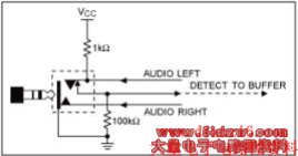
Figure 1. An automatic jack-detection circuit.
Headset Detection
The audio socket in Figure 1 is designed to handle the popular three-conductor audio plug. This plug connects either to a stereo headphone or a mono headset with microphone. You can easily differentiate between the stereo and mono-plus-microphone headset by using the circuits discussed below. These circuits leverage the fact that headphone resistance is low (usually 8Ω, 16Ω, or 32Ω) and that microphone resistance is high (600Ω to 10kΩ).
A brief introduction to the common audio jack and the electret microphone is helpful in understanding these circuits. In a three-conductor audio jack (Figure 2), the "tip" carries the left-channel audio for a stereo headphone or the microphone connection for a mono headset with microphone. For stereo headphones, "ring" connects to the right channel and "sleeve" to ground. For a mono headset with microphone, ring connects to the input audio channel for the mono microphone and sleeve connects to ground.
Figure 2. A three-conductor audio jack.
Electret Microphones
A typical electret microphone (Figure 3) has a condenser element whose capacitance varies in response to mechanical vibrations, thereby providing voltage variations proportional to the sound waves. Electret microphones have a permanent, built-in static charge and, therefore, require no external power source. They do, however, require a few volts to power an internal preamplifier FET.
Figure 3. An electrical model of an electret microphone.
The electret microphone appears as a constant-current sink that provides very high output impedance. Its high impedance is then converted by the FET preamplifier to the low impedance necessary for interfacing with the subsequent amplifier. Thus, the electret microphone's low cost, small size, and good sensitivity make it a good choice for applications like hands-free cell-phone headsets and computer sound cards.
The microphone is biased through a resistor (usually 1kΩ to 10kΩ) and a supply voltage that provides the necessary constant-bias current. This bias current ranges from 100µA to about 800µA, depending on the particular microphone and its manufacturer. The bias resistor is selected according to the applied supply voltage, the desired bias current, and the required sensitivity. Based on these factors, the necessary bias voltage varies from part to part and with operating conditions. A 2.2kΩ load resistor with 3V supply drawing 100µA, for example, develops a bias voltage of 2.78V. A similar resistor drawing 800µA under similar conditions develops a bias voltage of 1.24V.