标签:嵌入式系统开发,嵌入式开发,http://www.5idzw.com
利用液晶模拟器与MAX-IDE和IAR嵌入式工作台开发环境-,http://www.5idzw.com
Abstract: This application note describes how to use the LCD simulator on the MAX-IDE and IAR Embedded Workbench, and explains how to create the LCD memory map and LCD display panel. This article assumes that the reader knows the MAXQ20 core, and is aware of the MAX-IDE and IAR Embedded Workbench. By the end of this application note the user will understand the workings of the LCD simulator in both development environments.
The LCD simulator needs two inputs:
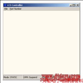
Figure 1. LCD simulator GUI.
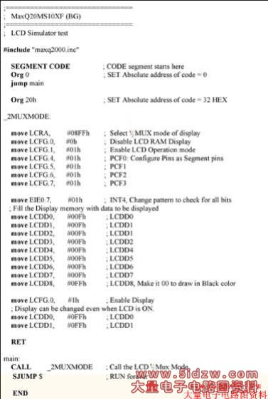
Table 1. Max-Ide_Lcd2MuxMode.asm Simulates the LCD Working in 1/2 Mux Mode in the MAX-IDE Environment
The above source code is available for download.
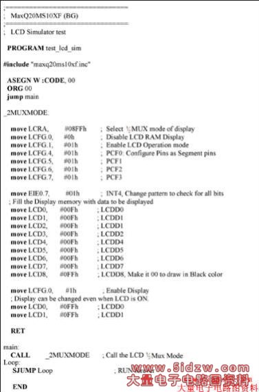
Table 2. IAR_Lcd2MuxMode.asm Simulates the LCD Working in 1/2 Mux Mode in the IAR Embedded Workbench
The above source code is available for download.
[LCDConfigFiles]
ConfigFile = config\lcd_config.xml
PinConfigFile = config\lcd_pin_config.xml
The user can override these files using the File→Open option of the GUI.
Abstract: This application note describes how to use the LCD simulator on the MAX-IDE and IAR Embedded Workbench, and explains how to create the LCD memory map and LCD display panel. This article assumes that the reader knows the MAXQ20 core, and is aware of the MAX-IDE and IAR Embedded Workbench. By the end of this application note the user will understand the workings of the LCD simulator in both development environments.
Introduction
The LCD simulator was developed on a Windows® platform with a GUI that simulates the digital behavior, but not the analog behavior, of the LCD controller. Readers can review application notes 3905, "MAX-IDE Simulator User's Guide for the MAXQ Microcontrollers," and 3378, "Getting started with the IAR Compiler and the MAXQ2000 Evaluation Kit" for information on working with MAX-IDE and IAR.Overview
The LCD simulator simulates the digital properties of the LCD controller, including: static, 1/2 mux, 1/3 mux, and 1/4 mux display modes; enabling/disabling LCD operation; and updating the LCD display with the display memory patterns. The LCD simulator ignores analog property changes, including: LCD drive voltage changes, display contrast adjustment, frame frequency effect.The LCD simulator needs two inputs:
- LCD segment configuration for static, 1/2, 1/3 and 1/4 display modes
- LCD pin configuration for static, 1/2, 1/3 and 1/4 display memory
Development Environment Settings for the LCD Simulator
The LCD simulator can be used on two environments, the MAX-IDE and the IAR Embedded Workbench.- MAX-IDE Settings
Some MAXQ® devices are configured and installed during the MAX-IDE installation. You can get the list of those devices from the Device→Options menu. Among these devices, the MAXQ2000 and MAXQ3210 have an LCD controller peripheral. Follow the steps below to create the project for simulation.- a. Create a Project. This procedure is explained in application note 3905 (see above) on the MAX-IDE simulator.
b. Add a file that tests the functionality of LCD controller. The file code is shown in Table 1.
c. Select Device→MAXQ2000→OK.
d. Under the Device menu, click on LCD Simulator and the LCD GUI will be displayed, as seen in Figure 1. - IAR IDE Settings
Some MAXQ devices' DDF (Device Description File), SFR, and ROM files are installed under the $TOOLKIT_DIR$\config directory during IAR Embedded Workbench installation. Follow the steps below to create the project used for simulation.- a. Create a project. This procedure is explained in the application note 3378 (see above) on the IAR compiler.
b. Add a file that tests the functionality of the LCD controller. The code is shown in Table 2.
c. Open Project→Options and go to the C Spy Debugger panel.
d. Select Device Simulator from the options shown.
e. Select the ddf file of the device to be simulated. In this example the file is maxq200x.ddf under $TOOLKIT_DIR$\config.
f. If the program is assembly, uncheck the "Run to main" option and Check XLINK→Include→Ignore C STARTUP in the library.
g. Select the utility ROM routine (.hex) of the device to be simulated, i.e., maxq200x.hex
h. Press OK.
i. Press Debug to debug the program.
j. Peripherals simulated can be seen under the View Menu option.
k. Select the LCD peripheral and the LCD GUI will be displayed as in Figure 1.
Figure 1. LCD simulator GUI.
Table 1. Max-Ide_Lcd2MuxMode.asm Simulates the LCD Working in 1/2 Mux Mode in the MAX-IDE Environment
The above source code is available for download.
Table 2. IAR_Lcd2MuxMode.asm Simulates the LCD Working in 1/2 Mux Mode in the IAR Embedded Workbench
The above source code is available for download.
Working with the LCD Simulator
As mentioned above, the LCD simulator depends on two XML input files:- Segment Configuration File
- Pin Configuration File
- Segment Configuration File
This file defines the type of the LCD display panel as either 7-segment or alphanumeric. The user can design the LCD display type by editing the XML file. The file details each segment as line or dot or any other shape (all multiples of a line) for static, 1/2 mux, 1/3 mux, and 1/4 mux. Without this input file, the LCD simulator will not update the GUI. - Pin Configuration File
Each MAXQ controller with a LCD peripheral comes in different pin configuration that assigns a different pin number for static, 1/2 mux, 1/3 mux, and 1/4 mux. Also some segment pins are multiplexed with two different functions:- a. I/O function
b. External interrupt, with I/O having the low priority and external interrupt having the higher priority.
[LCDConfigFiles]
ConfigFile = config\lcd_config.xml
PinConfigFile = config\lcd_pin_config.xml
The user can override these files using the File→Open option of the GUI.
LCD Registers and Their Simulation
- LCD Register Adjust (LCRA): Selects one of the display modes: static, 1/2 mux, 1/3 mux, and 1/4 mux. Changes to this register will be reflected on the status bar of the LCD GUI.
- LCD Configuration Register (LCFG): Each bit setting and the GUI status is described below:
Bit Settings GUI Changes DPE = 1 Display: ON DPE = 0 Display: OFF OPM = 1 OPM: Normal OPM = 0 OPM: Suspend
- LCDDx Registers: LCDDx registers can be updated when DPE = 0/1. Contents of LCDDx registers will be updated on the GUI when DPE = 1 and OPM = 1. Red will represent LCDs that are sourced; black represents LCDs that are present, but currently not sourced. LCDs not sourced can result from several factors:
- a. The PCFx bit of the LCFG registers is not SET, making the SEG pins work as I/O pins.
b. The LCD SEG pin that is multiplexed with an interrupt functionality is enabled.
c. The LCDDx register contains 0 in that bit position.
d. Moving the PC mouse on the display updates the COM and SEG.