标签:嵌入式系统开发,嵌入式开发,http://www.5idzw.com
利用液晶模拟器与MAX-IDE和IAR嵌入式工作台开发环境-,http://www.5idzw.com
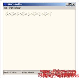
Figure 2. MAXQ2000 64-pin LCD panel.
After executing
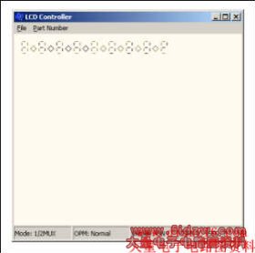
Figure 3. MAXQ2000 64-pin LCD panel display changes with DPE = 1.
The difference, you will notice, is that COM0:SEG2, COM0:SEG3, COM0:SEG6, and COM0:SEG7 change color from black to red which indicates that the LCDs are sourced.
With EIE0.7 enabled (SEG31 multiplexed with INT7), the GUI will look like:

Figure 4. MAXQ2000 64-pin LCD panel with SEG multiplexed with INT.
Compare Figure 2 with Figure 4. COM0:SEG31 and COM1:SEG31 are not sourced as LCD segments.
Note: The User can design/modify the LCD display panel and MAXQ pinout input of the LCD simulator. The XML input file can be opened in any editor and XML tag names used are self-explanatory.
GUI Changes for the Example Program
MAXQ2000 comes with three different pinout packages: 56, 68, and 100 pins. The test program (see Tables 1 and 2 above) tests the functionality of the MAXQ2000 68-pin package. Select the MAXQ2000 68-pin configuration from the part number list, and execute the test program. Note the GUI changes. move LCRA, #08FFh : Mode: 1/2 Mux
move LCFG.0, #0h : Display: OFF
move LCFG.1, #01h : OPM: Normal
move LCFG.4, #01h : PCF0: Configures I/O pins as segment pins
move LCFG.5, #01h : PCF1: Configures I/O pins as segment pins
move LCFG.6, #01h : PCF2: Configures I/O pins as segment pins
move LCFG.7, #01h : PCF3: Configures I/O pins as segment pins
move EIE0.7, #01h : Enables Interrupt Function of INT7, Comment
: /uncomment to see the MUX behavior of SEG pins
The display pattern is moved from the LCDD0 register to the LCDD8 register. A 1 represents the segments to be sourced, and a 0 represents segments that will not be sourced. move LCFG.0, #1h : Display: ONWith EIE0.7 disabled (comment move EIE0.7, #01h) and after executing the "move LCFG.0, #1" statement, the GUI display will look like Figure 3.
Figure 2. MAXQ2000 64-pin LCD panel.
After executing
move LCD0, #0ffh
move LCD1, #0ffh
The GUI will look like:
Figure 3. MAXQ2000 64-pin LCD panel display changes with DPE = 1.
The difference, you will notice, is that COM0:SEG2, COM0:SEG3, COM0:SEG6, and COM0:SEG7 change color from black to red which indicates that the LCDs are sourced.
With EIE0.7 enabled (SEG31 multiplexed with INT7), the GUI will look like:
Figure 4. MAXQ2000 64-pin LCD panel with SEG multiplexed with INT.
Compare Figure 2 with Figure 4. COM0:SEG31 and COM1:SEG31 are not sourced as LCD segments.
Note: The User can design/modify the LCD display panel and MAXQ pinout input of the LCD simulator. The XML input file can be opened in any editor and XML tag names used are self-explanatory.
Conclusion
The MAXQ device simulator can be used to develop and debug the LCD simulator for MAXQ10 and MAXQ20 microcontrollers. The application developed is then ready to run on the hardware.MAXQ is a registered trademark of Maxim Integrated Products, Inc.
<-- END: DB HTML -->