Measuring Temperature with the MAX1358 Data Acquisition System
Abstract: This application note explains how to use the internal and external temperature sensors on the MAX1358 data acquisition system. The temperature circuits for the / are identical, therefore any reference to the MAX1358 also applies to the MAX1359 and MAX1360. A step-by-step approach guides the user through the setup, measurement, and calculation of the temperature.
Introduction
The data acquisition system can measure temperature using an internal or external transistor PN junction. Figure 1 shows the internal temperature circuit and the external circuit. A constant current is supplied by the current source to produce a voltage (VBE) across the transistor. The current source can be programmed to produce up to four currents. For each current the voltage drop across the transistor is measured using the integrated ADC. The ADC has inputs for TEMP+, TEMP-, AIN1, AIN2, and AGND. These measured values are used in an equation to determine the junction temperature.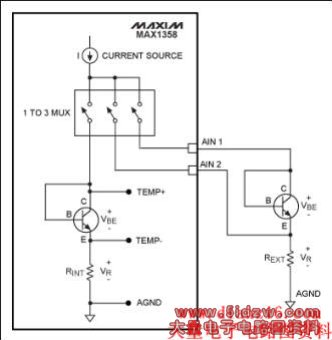
Figure 1. MAX1358 internal/external temperature measurement circuit.
Internal Four-Current Method
The internal four-current method requires eight measurements to be used in the temperature-measurement equation. Equation 1 below is used for four-current measurement.
Equation 1. Four-current temperature measurement equation.
Substituting for I1, I2, I3, and I4 in the denominator:
Where:
TMEAS = temperature in Kelvin
q = electron Charge = 1.60219 × 10⁻¹⁹ Coulombs
NVBE1 = ADC reading with I1 as current source
NVBE2 = ADC reading with I2 as current source
NVBE3 = ADC reading with I3 as current source
NVBE4 = ADC reading with I4 as current source
VREF = ADC reference voltage = 1.251V (typ)
n = diode ideality = 1.000 (typ)
k = Boltzmann's constant = 1.3807 × 10⁻²³ Joules/Kelvin
I1 = Current source low setting (4µA)
I2 = Current source high setting (60µA)
I3= Current source high setting (64µA)
I4 = Current source high setting (120µA)
NVR1 = ADC reading with I1 as current source
NVR2 = ADC reading with I2 as current source
NVR3 = ADC reading with I3 as current source
NVR4 = ADC reading with I4 as current source
216 = Number of ADC steps for MAX1358 16-bit ADC
To convert the measured temperature in Kelvin to degrees Celsius, the following formula is used:
°C = K - 273.15
Procedure Using the Internal Transistor
The procedure for measuring the voltages across the internal transistor and internal resistor applies a current from the current source, and measures the resulting VBE and VR.
Step 1. Enable the Reference and ADC
Enable the internal 1.251V reference and the reference buffer with a gain of 1.0 by setting REFV[1:0] bits to 0x01 in the REF_SDC register.
Enable the ADC by setting the ADCE bit in the ADC register. The internal reference and ADC are enabled. Note: The ADC is set with the default parameters of unipolar, normal polarity, single conversion, internal reference, unity gain, 10 samples per second, and normal conversion.
Step 2. Calibrate the ADC
Set the ADC conversion mode to Self Offset and Gain Calibration by setting the Mode[2:0] bits to 0x07 in the ADC register. Start an ADC conversion by setting the STRT bit in the ADC register. The ADC is now calibrated. The Mode[2:0] bits in the ADC register are automatically cleared. This returns the ADC to normal operation.
Step 3. Set the Current Source for the Internal Temperature Sensor
Set the current source for the internal temperature sensor by setting the IMUX[1:0] bits to 0x01 in the TEMP_CTRL register.
Step 4. Set the Current Source for I1 (4µA)
Set the current source for I1 by setting the IVAL[1:0] bits to 0x00 in the TEMP_CTRL register.
Step 5. Set the ADC Input for TEMP+ to TEMP-
Set the ADC positive input multiplexer for TEMP+ by setting MUXP[3:0] to 0x07 in the MUX register. Set the ADC negative multiplexer for TEMP- by setting MUXN[3:0] to 0x00 in the MUX register.
Step 6. Measure VBE1 using the ADC
The VBE1 voltage is measured from the TEMP+ to the TEMP- inputs to the ADC. The ADC is already configured and only needs to convert to get the resulting VBE1 voltage. To start the ADC conversion, set the STRT bit in the ADC register. The ADC will do a conversion and the result will be in the DATA register. Read the DATA register value and save as a 16-bit integer named VBE1 for later calculation.
Step 7. Set the ADC Input for VR1
Set the ADC positive input multiplexer for AGND by setting MUXP[3:0] to 0x09 in the MUX register. Set the ADC negative multiplexer for TEMP- by setting MUXN[3:0] to 0x00 in the MUX register (same as step 5). To measure the TEMP- input relative to AGND, the polarity flipper bit is used. Set the POL bit in the ADC register. The ADC is now setup with TEMP- as its positive input and AGND as its negative input.
Step 8. Measure VR1 using the ADC
To start the ADC conversion, set the STRT bit in the ADC register. The ADC will do a conversion and the result will be in the DATA register. Read the DATA register value and save as a 16-bit integer named VR1 for later calculation.
Step 9. Set the Current Source for I2 (60µA)
Set the current source for I2 by setting the IVAL[1:0] bits to 0x01 in the TEMP_CTRL register.