Detailed Design Description
The reference design consists of a single, carefully tuned box enclosure containing all of the electronics and speaker hardware. Only an external power supply and a signal source are required to complete the system.
The design features two 2in loudspeaker drivers for the left and right channels, and a 5in loudspeaker for the subwoofer. A single MAX9736B is used in stereo mode for the left/right channels and a MAX9736A is used in mono mode for the subwoofer channel. The detailed description here is divided into two sections: electronic circuit description and speakers/physical enclosure description.
Electronic Circuit Description
The electronics of the reference design comprise two sections, the left/right and subwoofer. Each section has three stages: input, EQ, and power. See Figure 1.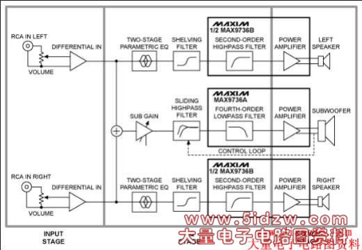
Figure 1. Electrical circuit block diagram features the MAX9736 Class D audio amplifier. The design has an input, EQ, and power stage.
Input Stage
The input stage is common to both the left/right and subwoofer sections. A stereo, log-taper potentiometer is used as a volume control to adjust the signal level to the preamplifier. To avoid ground loops, the input is sensed differentially and the RCA input connectors are not directly connected to the system ground. A 100Ω resistor is used to reduce the common-mode voltage; U3-A and U3-D (see schematics below) perform differential-to-single-ended conversion with a gain of 2. The outputs of the input stage are referred to VREF, the reference voltage of power amplifier U2 which is buffered using U5-D.
EQ Stage
After the input stage, the left and right signals are passed to a two-stage parametric EQ built around U3-B (for left) and U3-C (for right). Each parametric EQ uses an op-amp gyrator to simulate an inductor in an LC-series resonant circuit. The series circuit has two access points for either attenuation or boost, and the access points are realized by two different capacitors. C105 and C106, for example, are the boost and attenuation points for the first parametric EQ band for the left channel. If only C106 is used (and C105 is not stuffed), the resonant circuit forms a voltage-divider in combination with the series resistor R105 (10kΩ), and the resonant frequency is attenuated. Conversely, if only C105 is used, the feedback is reduced, resulting in a boost at the resonant frequency. If neither of the capacitors is used, then the band is disabled.
The resonant frequency, f0, can be calculated using the equation:
f0 = 1/(2 × π × √(L0 × C0))
Where:
L0 = R108 × C107 × R107
C0 = C105
And the Q is:
Q0 = √(L0/(C0 × R0²))
A third EQ band is added that realizes a shelving filter and only needs an RC: one capacitor (C113 for boost; C114 for attenuation) and one resistor (R111).
As a stereo Class D IC, the MAX9736 also features two integrated op amps at the input. Available to use for general filtering, in this reference design those op amps are used to build a second-order highpass filter for the left/right channels. The op amps have their negative inputs and outputs accessible, so a multiple-feedback inverting filter configuration is used. C116/C216 are for blocking the DC-input voltage to reduce output offset.
Power Stage
The design features three channels of speaker power amplification. A MAX9736B is configured in stereo mode to drive the left and right speakers, and can provide 2 × 11W into 4Ω. For the third channel, a MAX9736A is configured as a mono subwoofer amplifier.
In mono mode, the two Class D outputs of the MAX9736A are connected in parallel to allow for higher output power. In mono mode the subwoofer channel can deliver 30W into 4Ω (VDD = 19V). The input stage for the subwoofer channel is the same as that used for the left and right channels. After the input stage, the left and right signals are then summed using U5-B to create the mono subwoofer channel. R303 is used to set the subwoofer channel gain at the summing amp.
To enable a maximally flat response down to very low frequencies, the system is configured with a sixth-order filtered alignment for the subwoofer. This approach means that the fourth-order highpass response of the vented speaker is supplemented with a second-order electrical highpass in the active circuitry. U5-C is used to realize the noninverting Sallen-Key, second-order highpass filter for the subwoofer.
This system requires a high Q, which leads to 13dB of boost at 40Hz. To avoid overloading the speaker and amplifier, the Sallen-Key filter is set up to act as a sliding highpass; the filter acts dynamically as the amplifier output reaches its limit. The value of input resistor R305 is designed to reduce automatically (using the opto-coupled FET, U7) to a value so that the filter Q is lowered to 0.5, resulting in no boost at all.
The peak output voltage of the subwoofer amplifier, U2, controls the signal to the opto-FET. D6 and C16 form a peak detector, which senses the output peak level with a fast attack time. The operating threshold for the peak detector can be adjustable or fixed, depending on whether R7 is stuffed or R8/R9 are stuffed. The LED D5 turns on when this control circuit is active.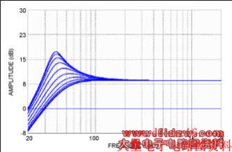
Figure 2. Simulation results of the dynamic bass boost from the subwoofer channel. The Q of the highpass filter is reduced while the cutoff frequency is also increased, as the subwoofer level approaches its limit.
The two op amps built into the MAX9736A are configured into a fourth-order lowpass subwoofer filter that complements the highpass filter used for the left/right channels.