标签:模拟电子技术基础,模拟电子电路,http://www.5idzw.com
Reduce System Cost for Advance,http://www.5idzw.com
Figure 1. Typical power-grid monitoring application using simultaneous-sampling ADCs.
As Figure 1 illustrates, the ADCs simultaneously measure the three phases and neutral voltages and currents. By performing digital processing on the sampled and digitally converted data, the active-, reactive-, apparent-energy, and power-factor parameters can be found and the line loads can be dynamically adjusted to correct for power factor. The result is increased power efficiency. The execution of a FFT (fast Fourier transform) on the sampled data can allow frequency and harmonic distortion metering to be achieved, while highlighting information such as system losses and the effects of unwanted noise.
The ADC's dynamic range for voltage measurement can be calculated from the maximum and nominal voltages to be monitored, and from the required accuracy for power measurements. For example, if a design must measure a 1.5kV (1500V) temporary overvoltage (under a fault condition) with a nominal 220V voltage measurement and 0.2% specified accuracy, then the total dynamic range of the voltage-measurement subsystem will need to be at least:
Current-sensing requirements also affect ADC specifications. If the design requirements for power monitoring are the typical 100A:10A (10A nominal and 100A maximum) and Class 0.2 (0.2%), then the total dynamic range of the current-measurement subsystem will need to be:
Several ADC solutions meet the rigorous standards of these power-grid monitoring applications. A majority of these targeted solutions are 6-channel, 16-bit simultaneous-sampling ADCs with sample rates up to 250ksps.
Several companies offer chips with up to six low-power 250ksps SAR (successive-approximation register)-type ADCs. Maxim offers the *, which integrates eight high-precision, low-power, 16-bit, 250ksps SAR ADCs in a single package. The MAX11046 achieves greater than 90dB signal-to-noise ratio.
If the ADC has a high ZIN like the MAX11046, it can interface directly with voltage and current-measurement transformers. That interface often eliminates the need for external precision instrumentation amplifiers, or buffers. The design therefore saves system cost, board area, and power. Figure 2 shows an application example for a single-phase monitoring system based on the MAX11046 EV (evaluation) kit board connected to powerline monitor transformers. The schematic shows the simple cost and space-efficient interface between the powerline transformers and the simultaneous-sampling, multichannel data converter. For a three-phase power system, this circuitry is replicated for each phase and the neutral.
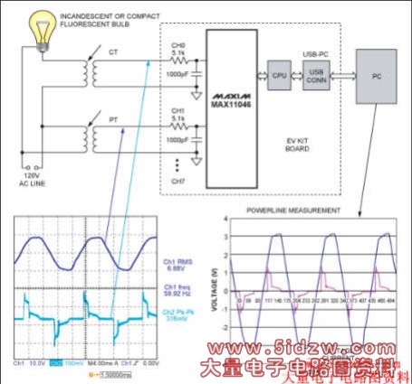
Figure 2. Multichannel simultaneous-sampling ADCs such as the Maxim MAX11046 simplify the design of advanced power-monitoring systems. A single-phase monitoring solution is shown in this example.
Traditionally, signal-phase adjustment using simultaneous-sampling, multichannel 16-bit ADCs has been addressed digitally as a postprocessing step performed on the ADC's output data. Maxim's MAX11046 high-precision data converter handles phase adjustment in this manner. With such an ADC, continuous software overhead is required to address signal-phase adjustment.
Some of today's ADC solutions offer input-phase adjustments of 0 to 333µs with the delay independently settable per channel in 1.33µs steps. This design eliminates the software overhead mentioned above. One such device, the 24-bit, 4-channel sigma-delta ADC, provides this capability plus high-precision, simultaneous sampling of as many as 32 channels using a built-in cascade feature. Each channel includes an adjustable sampling phase that permits internal compensation for phase shift due to external transformers or filters at the inputs. An active-low SYNC input allows periodic alignment of the conversion timing for up to eight devices with a remote timing source.
,Reduce System Cost for Advance
Figure 1. Typical power-grid monitoring application using simultaneous-sampling ADCs.
As Figure 1 illustrates, the ADCs simultaneously measure the three phases and neutral voltages and currents. By performing digital processing on the sampled and digitally converted data, the active-, reactive-, apparent-energy, and power-factor parameters can be found and the line loads can be dynamically adjusted to correct for power factor. The result is increased power efficiency. The execution of a FFT (fast Fourier transform) on the sampled data can allow frequency and harmonic distortion metering to be achieved, while highlighting information such as system losses and the effects of unwanted noise.
Power-Monitoring System Requirements
Power-monitoring equipment must measure instantaneous current and voltage values with sample rates up to 60Hz × 256 samples, or greater than 15,360sps (samples per second), to accommodate the standard's requirements. This requirement and the need for precision up to 90dB form the basis for selecting the ADC used in the system.The ADC's dynamic range for voltage measurement can be calculated from the maximum and nominal voltages to be monitored, and from the required accuracy for power measurements. For example, if a design must measure a 1.5kV (1500V) temporary overvoltage (under a fault condition) with a nominal 220V voltage measurement and 0.2% specified accuracy, then the total dynamic range of the voltage-measurement subsystem will need to be at least:
20log ((1500/220) × 2000) = 83dBNote: In all these calculations, the required design accuracy is assumed to be 0.05%, which is better than the standard's 0.2% accuracy requirements. This design margin is used to ensure compliance to the standard.
Current-sensing requirements also affect ADC specifications. If the design requirements for power monitoring are the typical 100A:10A (10A nominal and 100A maximum) and Class 0.2 (0.2%), then the total dynamic range of the current-measurement subsystem will need to be:
20log ((100/10) × 2000) = 86dBThese examples clearly demonstrate the need for higher performance in today's ADCs. To achieve an 86dB dynamic range, a 16-bit ADC with sampling rates of 16ksps or higher is essential. To ensure accurate 3-phase and neutral wye system current and voltage measurements, the ADC must sample up to eight channels simultaneously (four voltage and four current). Additionally, the ability to correct the current and voltage transformer-induced phase shift (or delays) is critical for systems trying to measure and correct power factor to maximize power efficiency.
ADC Alternatives
When selecting the right ADC for a power-grid monitoring application, designers must look beyond sample rates and standard requirements. Today they must also consider factors like effective input impedance (ZIN), signal-phase adjustment, and a small package size. Given these many system requirements, designers are turning to simultaneous-sampling, multichannel, high-performance ADCs for their powerline monitoring or multichannel SCADA (supervisory control and data acquisition) systems.Several ADC solutions meet the rigorous standards of these power-grid monitoring applications. A majority of these targeted solutions are 6-channel, 16-bit simultaneous-sampling ADCs with sample rates up to 250ksps.
Several companies offer chips with up to six low-power 250ksps SAR (successive-approximation register)-type ADCs. Maxim offers the *, which integrates eight high-precision, low-power, 16-bit, 250ksps SAR ADCs in a single package. The MAX11046 achieves greater than 90dB signal-to-noise ratio.
Effective Input Impedance (ZIN)
ZIN is dictated by the input capacitance and sampling frequency:ZIN = 1/(CIN × FSAMPLE)Where FSAMPLE is the sampling frequency and CIN = 15pF.
If the ADC has a high ZIN like the MAX11046, it can interface directly with voltage and current-measurement transformers. That interface often eliminates the need for external precision instrumentation amplifiers, or buffers. The design therefore saves system cost, board area, and power. Figure 2 shows an application example for a single-phase monitoring system based on the MAX11046 EV (evaluation) kit board connected to powerline monitor transformers. The schematic shows the simple cost and space-efficient interface between the powerline transformers and the simultaneous-sampling, multichannel data converter. For a three-phase power system, this circuitry is replicated for each phase and the neutral.
Figure 2. Multichannel simultaneous-sampling ADCs such as the Maxim MAX11046 simplify the design of advanced power-monitoring systems. A single-phase monitoring solution is shown in this example.
Signal-Phase Adjustment
As high voltage goes through the transformer and transitions to a lower voltage, a phase shift (or delay) occurs. This delay creates a significant problem for power-management or power-monitoring applications. To address this, designers can adjust phase in software at the backend or they can realign the signals inside the ADC upfront. Deskewing the voltage and current signals allows for true and accurate measurement of the power factor in the wye configuration. Shifts in phase from the 120o separation of the three phases represent lost power. Once the power factor is accurately measured, it can be corrected to make the grid exponentially more efficient.Traditionally, signal-phase adjustment using simultaneous-sampling, multichannel 16-bit ADCs has been addressed digitally as a postprocessing step performed on the ADC's output data. Maxim's MAX11046 high-precision data converter handles phase adjustment in this manner. With such an ADC, continuous software overhead is required to address signal-phase adjustment.
Some of today's ADC solutions offer input-phase adjustments of 0 to 333µs with the delay independently settable per channel in 1.33µs steps. This design eliminates the software overhead mentioned above. One such device, the 24-bit, 4-channel sigma-delta ADC, provides this capability plus high-precision, simultaneous sampling of as many as 32 channels using a built-in cascade feature. Each channel includes an adjustable sampling phase that permits internal compensation for phase shift due to external transformers or filters at the inputs. An active-low SYNC input allows periodic alignment of the conversion timing for up to eight devices with a remote timing source.
,Reduce System Cost for Advance