标签:汽车音响功放,音响功放电路,http://www.5idzw.com
改善立体声性能与Active偏置-Improve Stereo Performance with Active Biasing,http://www.5idzw.com
Figure 6. Passive bias network with 10µF capacitor.
The values of R1 and R2 can be reduced at the expense of increased DC current. That is not going to be practical. Obviously, we are depending on C2 getting the impedance down very low before the audio band. For 100Hz and 95dB, you find that the capacitor is again unrealistic. For values of 10kΩ, 10kΩ, and a somewhat large 100µF capacitor, the resulting attenuation curve is shown in Figure 7. The solution is to use an active circuit, as will be discussed later in this article.
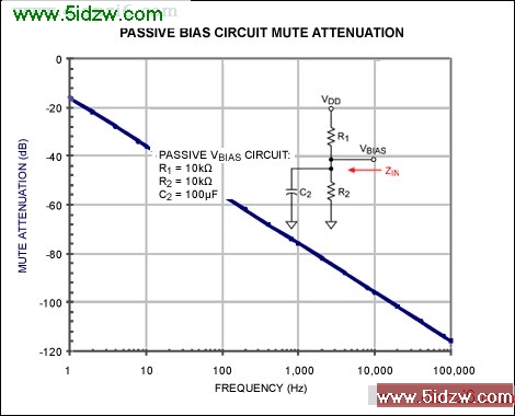
Figure 7. Passive bias network with a 100 µF capacitor.
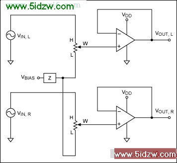
Figure 8. Passive bias networks and stereo signals.
The finite bias impedance again creates a signal voltage on the L terminal of the digital potentiometer when there is an input on the H terminal. However, this time we are sharing the bias generator, so we will get a signal at both VOUT pins from a signal on either the left or the right VIN. The in-channel signal will appear as poor mute attenuation or a failure to follow the attenuation curve. The opposite-channel signal will appear as crosstalk or a loss of stereo separation.
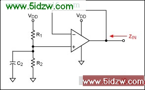
Figure 9. Op amp buffers bias voltage-divider.
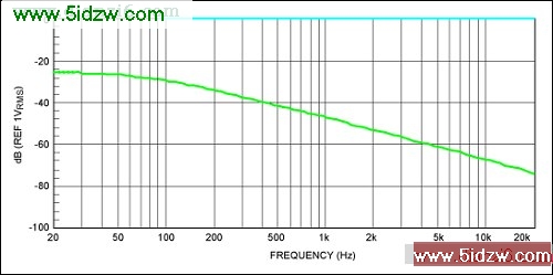
Figure 10. Full-scale and mute responses with passive biasing of digital Potentiometer.
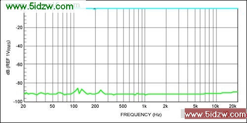
Figure 11. Full-scale and mute responses with active biasing of digital potentiometer.
The active circuit can have higher resistors since only a noninverting buffer is loading it. In this case, two 100kΩ resistors can be used without affecting the active bias curve. This makes the continuous battery drain just 25µA.
![Figure 12. The MAX5486 volume control IC includes V<sub style=]() BIAS and wiper buffers required for audio applications." src="/adianzi/UploadPic/2009-8/2009817115251642.jpg">
BIAS and wiper buffers required for audio applications." src="/adianzi/UploadPic/2009-8/2009817115251642.jpg">
Figure 12. The MAX5486 volume control IC includes VBIAS and wiper buffers required for audio applications.
Various members of the Maxim family of volume-control ICs provide solutions that can be directly interfaced to a microprocessor, pushbuttons, rotary encoders, or even infrared remote controls. Additional features like zero crossing synchronized wiper movements make them optimal for audio applications.
A similar article appeared was published in December 2008 on the Electronic Products Magazine website.
Figure 6. Passive bias network with 10µF capacitor.
Other Problems
Although we have been analyzing this problem at the mute setting (wiper at the L terminal), it is apparent that the finite VBIAS impedance will affect all of the potentiometer settings. The effect will be seen as an increasingly inaccurate attenuation curve as the low end is approached.How Can the Problem Be Corrected?
So, how do we get the impedance down and the mute performance more like 90dB or better? To reach 90dB, we need to be in the single-digit Ohms range.The values of R1 and R2 can be reduced at the expense of increased DC current. That is not going to be practical. Obviously, we are depending on C2 getting the impedance down very low before the audio band. For 100Hz and 95dB, you find that the capacitor is again unrealistic. For values of 10kΩ, 10kΩ, and a somewhat large 100µF capacitor, the resulting attenuation curve is shown in Figure 7. The solution is to use an active circuit, as will be discussed later in this article.
Figure 7. Passive bias network with a 100 µF capacitor.
Stereo Circuit
Before we discuss the active circuit fix, let us take a look at what happens in a stereo design. For a stereo signal that is sharing a passive bias generator, the mute or feedthrough problem occurs. There is, however, an additional problem: crosstalk. Crosstalk is the leakage of signal from the left (L) channel into the right (R) channel, or vice versa. Here is how it happens. When we share the bias line between L and R channels the circuit is as shown in Figure 8.Figure 8. Passive bias networks and stereo signals.
The finite bias impedance again creates a signal voltage on the L terminal of the digital potentiometer when there is an input on the H terminal. However, this time we are sharing the bias generator, so we will get a signal at both VOUT pins from a signal on either the left or the right VIN. The in-channel signal will appear as poor mute attenuation or a failure to follow the attenuation curve. The opposite-channel signal will appear as crosstalk or a loss of stereo separation.
Active Bias
There is a solution to all of these problems: provide a very stiff or low-impedance source of VBIAS. A typical circuit is shown in Figure 9. The divided-down VDD is buffered by an op amp whose closed-loop output impedance is fractions of an Ohm. Using this circuit you can achieve results in the 90dB range with careful design.Figure 9. Op amp buffers bias voltage-divider.
Measurement Results
A test board was used to compare the passive and active approaches. Figures 10 and 11 illustrate typical performance achieved on a MAX5457-based test board for both passive and active circuits. The passive circuit is made of two 1kΩ resistors bypassed by 4.7µF. This results in a pole at 68Hz (calculated) and a continuous 2.5mA drain on the 5V supply.Figure 10. Full-scale and mute responses with passive biasing of digital Potentiometer.
Figure 11. Full-scale and mute responses with active biasing of digital potentiometer.
The active circuit can have higher resistors since only a noninverting buffer is loading it. In this case, two 100kΩ resistors can be used without affecting the active bias curve. This makes the continuous battery drain just 25µA.
Even Better―Integrate It!
As we have seen, the passive circuits have poor performance and add both cost and size. An active circuit that creates a buffered version of the resistor-divider works well, but adds the overhead of an op amp. Is there a way to have both small size and the best performance? It turns out that the answer is yes. A volume-control IC like the MAX5486 in Figure 12 is an all-in-one solution that includes this function together with the digital potentiometer in a single package.Figure 12. The MAX5486 volume control IC includes VBIAS and wiper buffers required for audio applications.
Various members of the Maxim family of volume-control ICs provide solutions that can be directly interfaced to a microprocessor, pushbuttons, rotary encoders, or even infrared remote controls. Additional features like zero crossing synchronized wiper movements make them optimal for audio applications.
A similar article appeared was published in December 2008 on the Electronic Products Magazine website.
<-- END: DB HTML -->